
HP 8640B Signal Generator Repair
S/N 2835A30360
Options 001 003
I’ve been looking for one of these puppies for awhile. I used one of these in my work in the mid-late 70’s, so I’ve been trying to find something broken but newer to bring back to glory. Considered by many as one of the finest signal generators ever manufactured, the 8640B has been around a long time, and its frequency stability and spectral purity is second to none.
I really wanted a 1Ghz unit, so started looking for one with the internal doubler option but nothing in decent cosmetic shape was to be had. No worries, I can use an external doubler, so I focused on the newest 8640B I could find.
I happened on an eBay auction that was pretty much in line with what I wanted, $150 on eBay, and it looked in really good condition besides being broken (The usual “turns on, lights up, cant check it” conversation ensued). I tried to get the s/n of the unit but the seller just wasn’t interested in that much work. Long story short, purchased the unit on eBay and waited.
The unit showed up in a large box that was dented on one corner, so I figured it had been UPS’ed along the way. After opening, the packing was at least worth a chuckle….
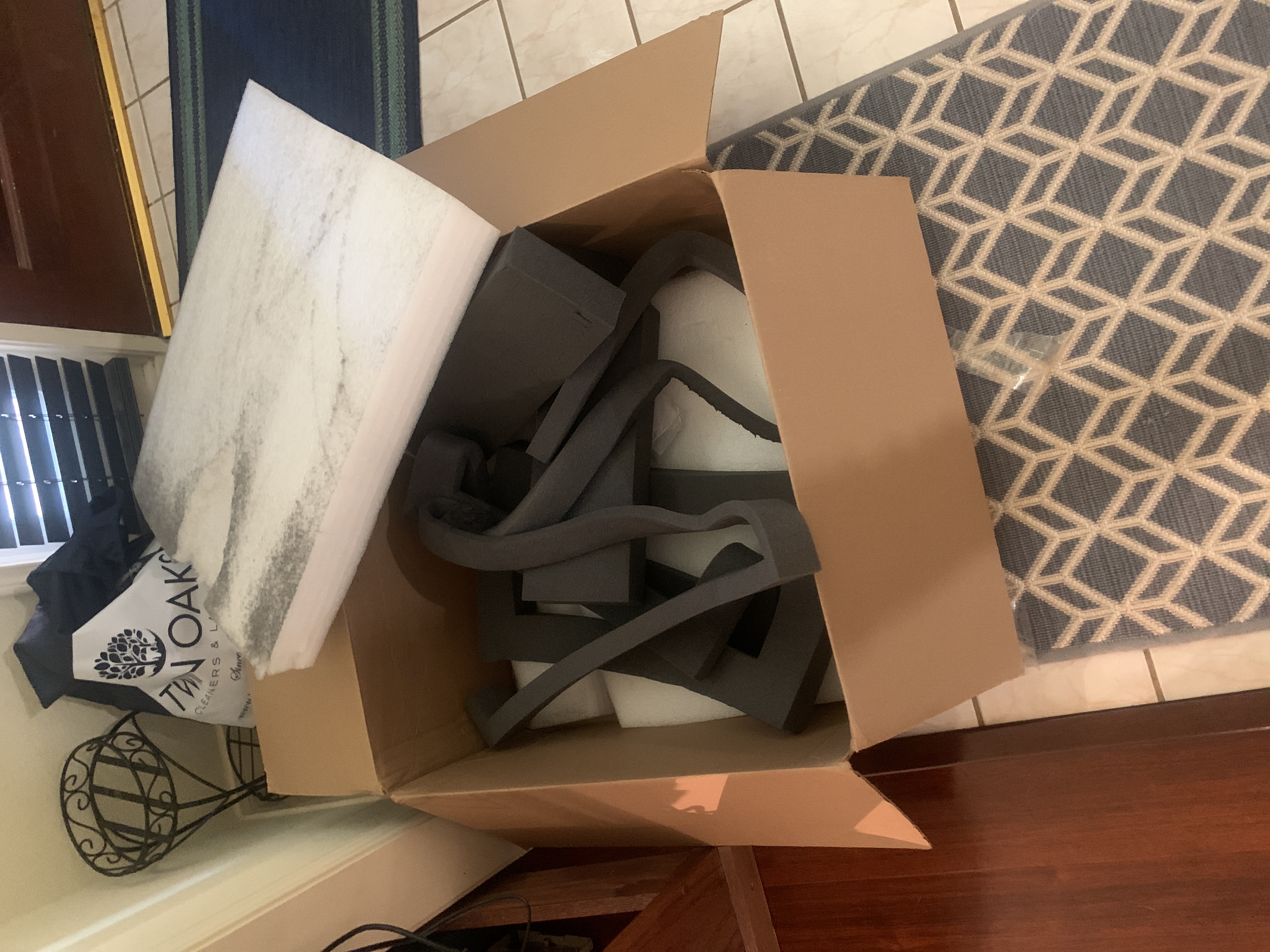
Looks like they had a bunch of foam laying around 🙂
The good news, despite the packaging all looked good. No broken knobs, front panel in great condition. Aluminum side rails were a little beat up from bench dragging, but the rack will hide all that anyway. Checked the configuration, Options 001 & 003 installed, that’s good. Pulled the serial number to get more info:
For serial numbers in the format xxyyAnnnnn adding 60 to xx is the year made, yy is the week, the letter is the country where made.
For S/N= 2835A30360 :
* 28 -> Made in 1988
* 35 -> Week # of last production change 48
* A = America, J -> Made in Japan, G = West Germany, U= United Kingdom
* 30360 actual serial number of instrument
The series prefix doesn’t represent the date of manufacture. Instead, it represents the date of the last production change that affects form, fit, or function, or for other modifications such as firmware version changes. They use the series prefix to tie production changes (changes in production documentation) to changes in customer documentation.
So that’s cool, it was built sometime after late 1988. That makes it 32 years old…a mere child for HP equipment.
Power Up
So let’s fire this thing up and see what condition it’s in.
Rummaged around and finally located a power cable, plugged it in and nothing.
Good, the power switch is off. Enable the power button (it sticks a bit but illuminates).
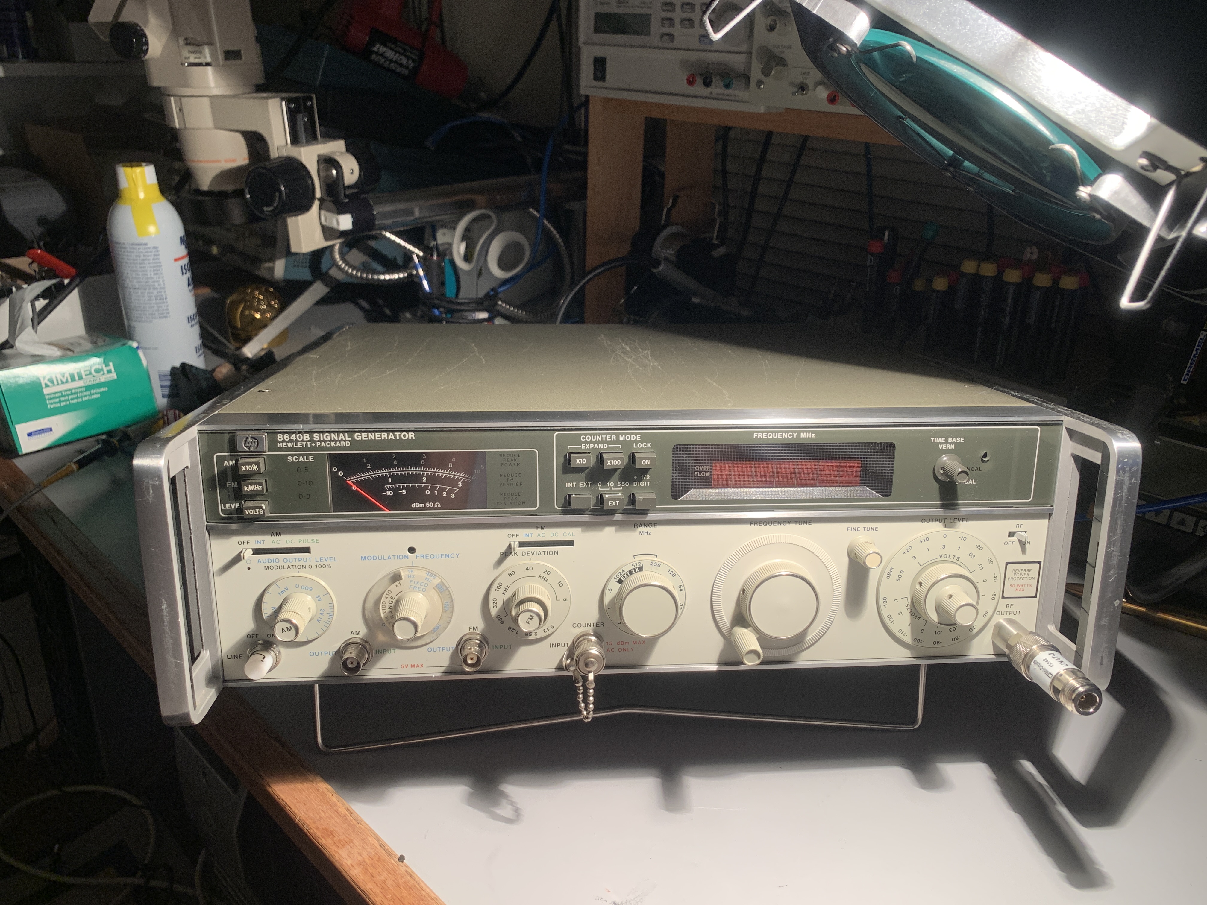
Counter reads zero, not good. I decided to stop here and have a poke around the internals since there was no RF.
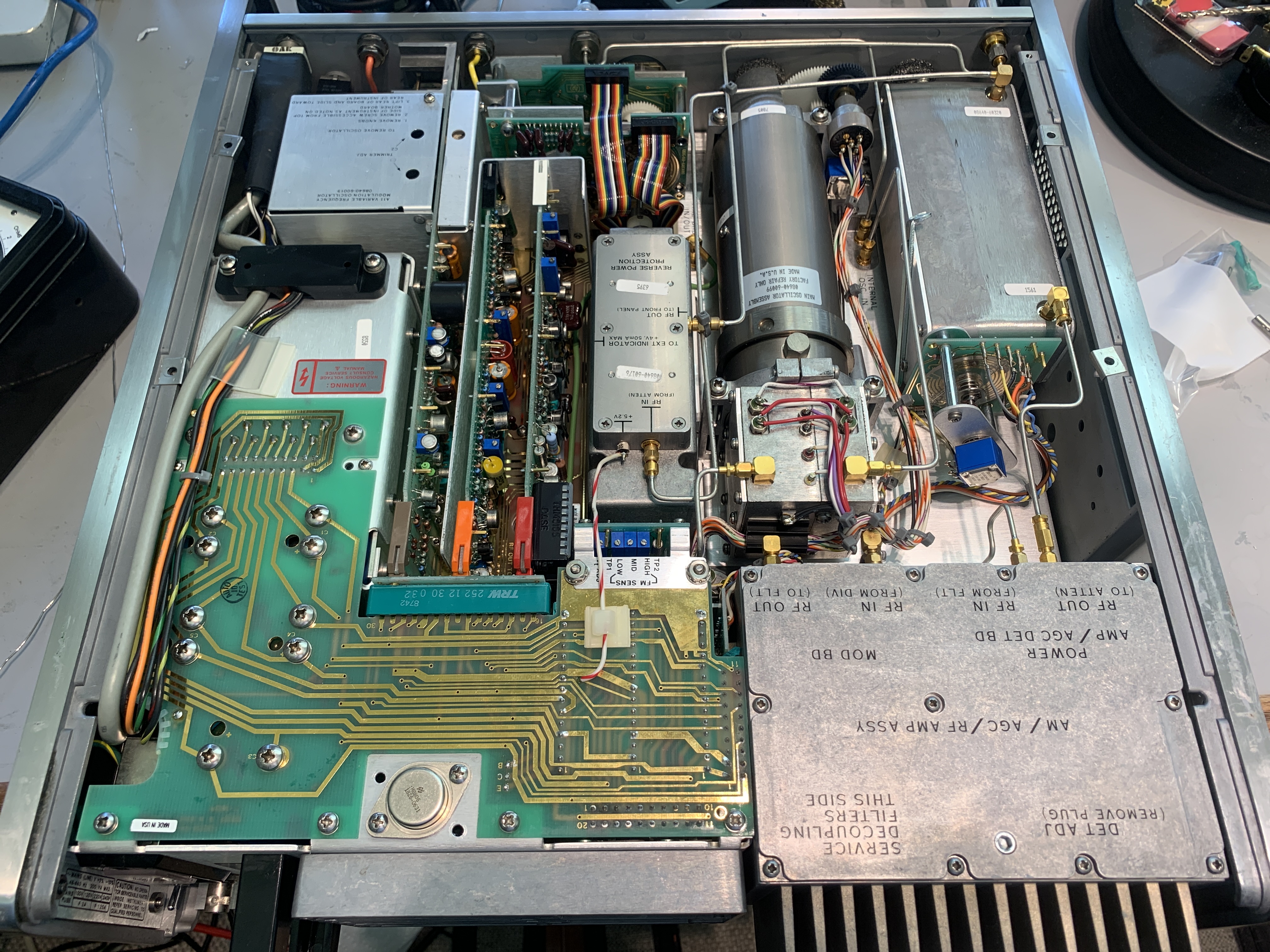
Pulled the top & bottom covers and hers what I found:
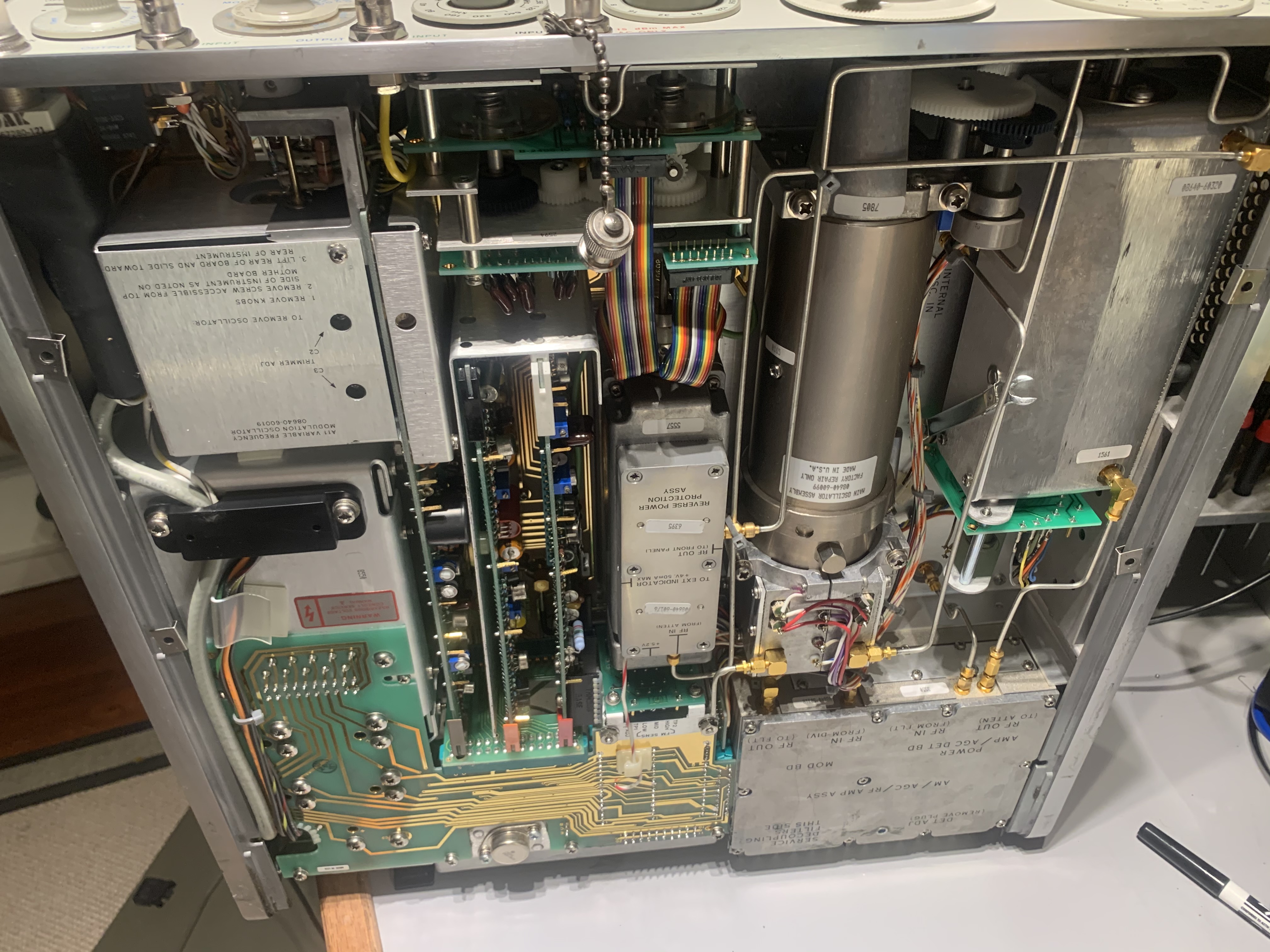
Is this gorgeous or what ? The pictures don’t do justice, this thing looks BRAND NEW with the covers removed ! Nothing obviously amiss, the range selector gears are all intact (I may swap to some custom metal gears before I’m done..the plastic ones WILL fail at some point. The range selector mechanism is also a bit sluggish and torquey so I’ve got to get in there sooner or later.
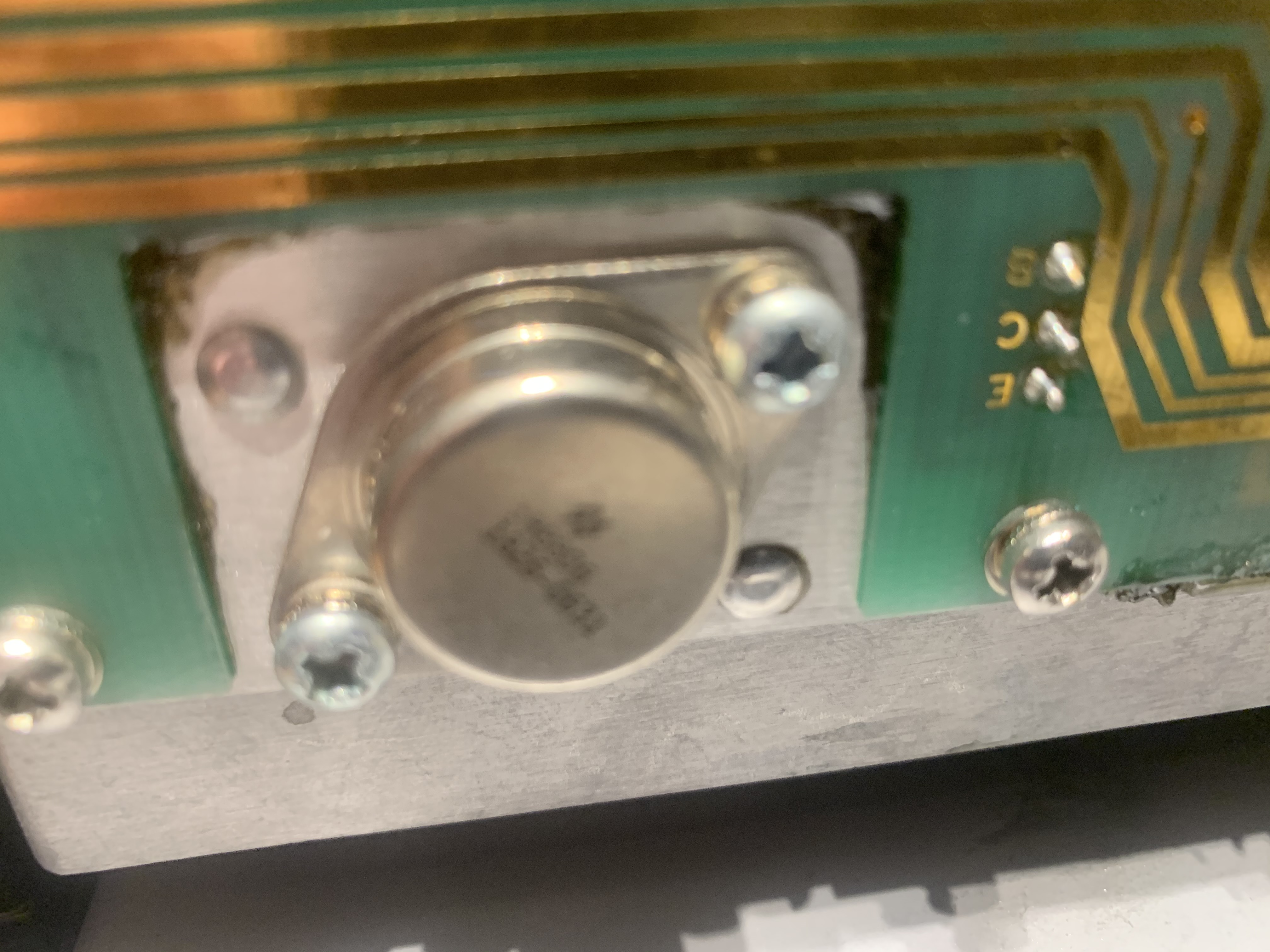
You see that TO-3 package on the very bottom mounted in a cutout on the power motherboard ? There is some sort of weird black goo along the edge.
And on the adjacent connector on the power motherboard:
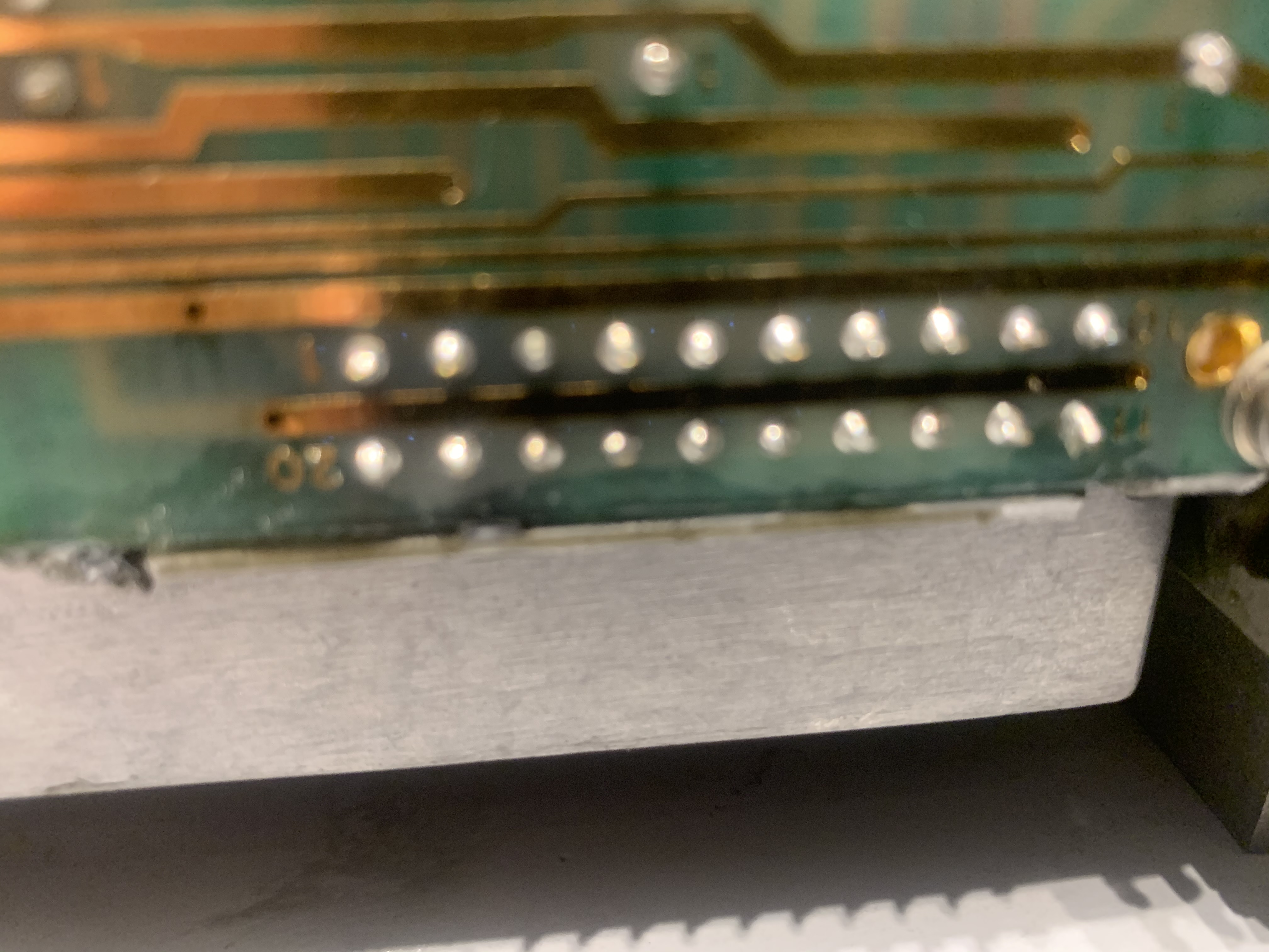
OK, so that doesn’t look too good. Now to figure out where its coming from. Flipping the unit over, I start realizing that gooey shit is everywhere.
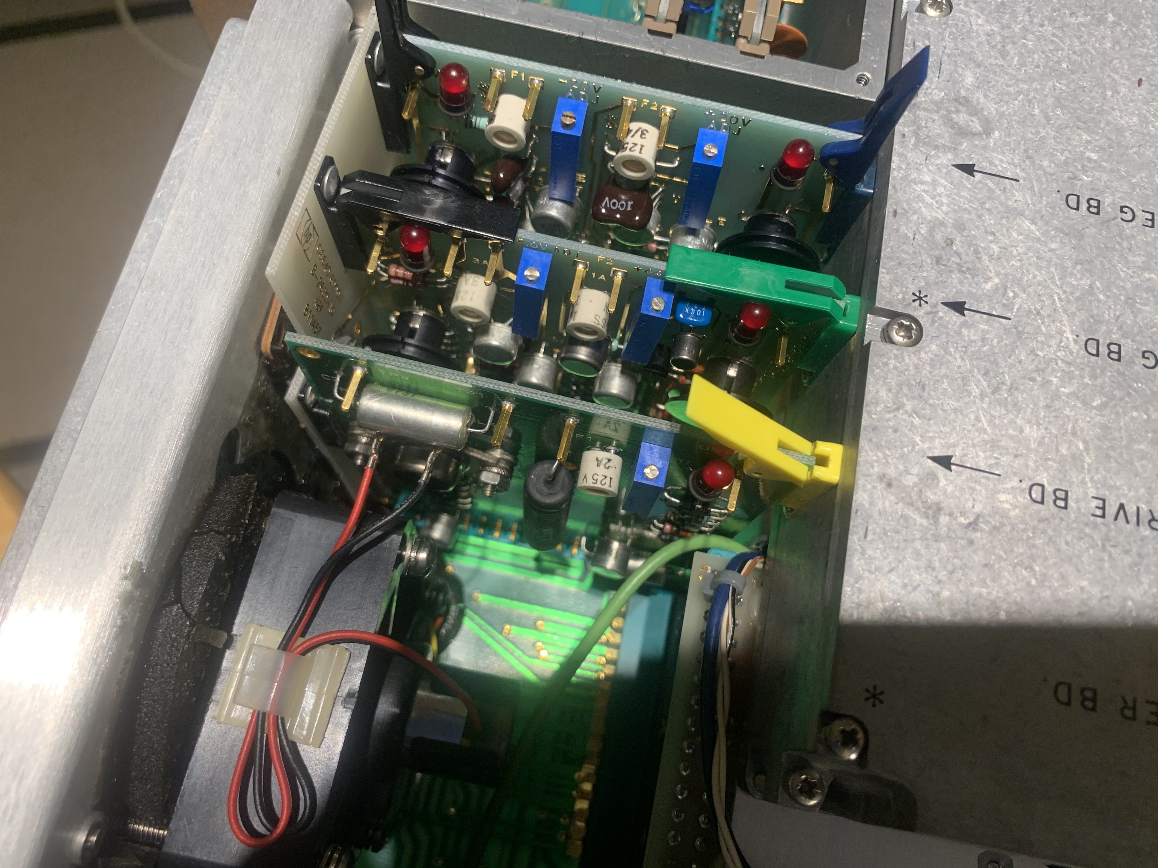
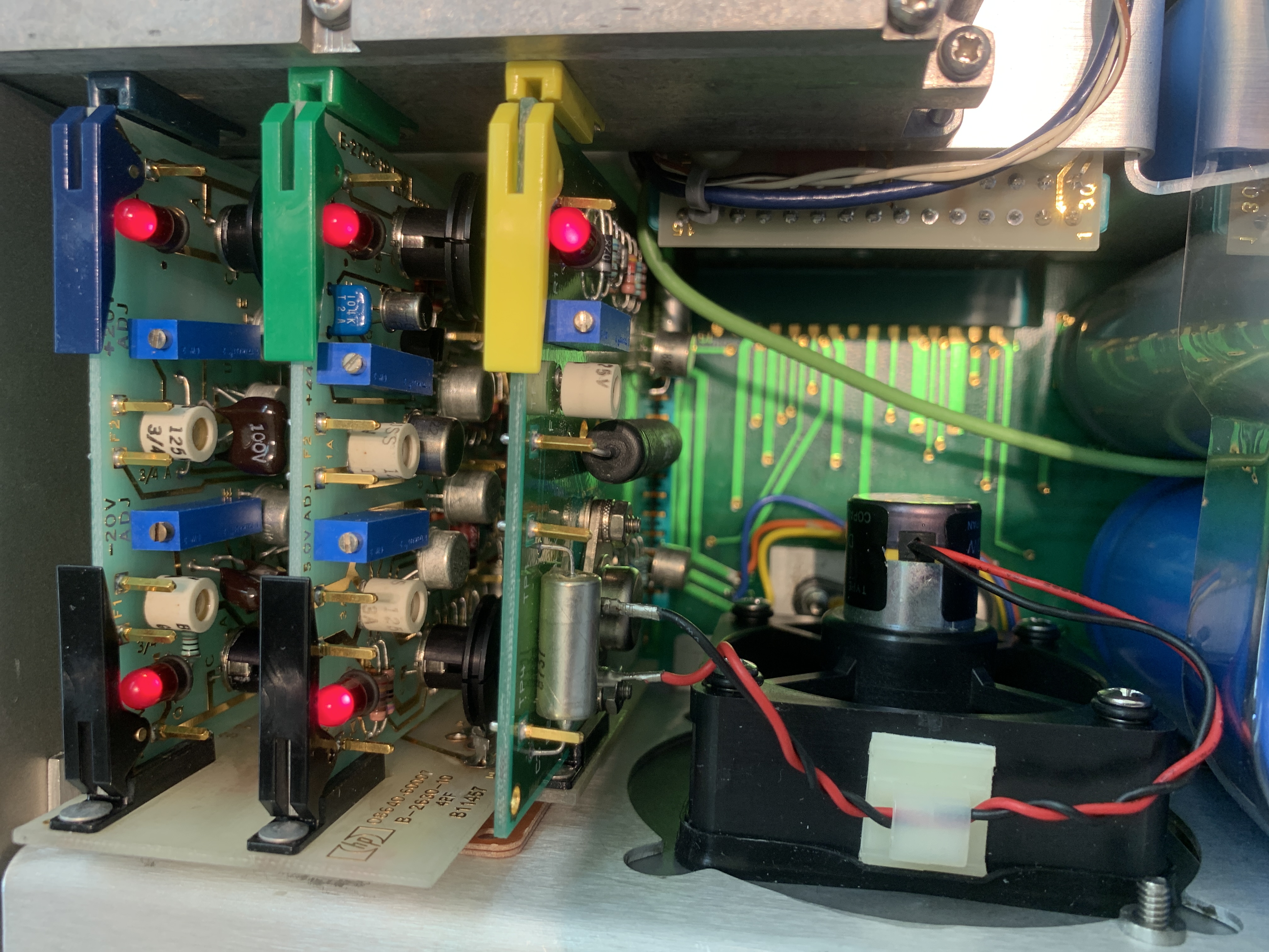
So here we are, looking at the power supply PWB’s. There is definitely something weird going on near the fan. First, that’s the first 2-wire fan I’ve seen in an HP3640B ever. And it seems to be driven by a new version of the fan controller card (the older ones had lots of wires for the 3 phases & sensors). This has a p/n of 08640-60392.
Looking further, there is this severely deteriorated foam rubber gasket at the fan to rear panel interface. And a big pool of viscous black goo, obviously the source of the goo leak on the opposite side. The fan attaches to the rear panel with 4 long bolts, all loose and rattling around. Time to pull all this down some more so we can see what we’re dealing with.
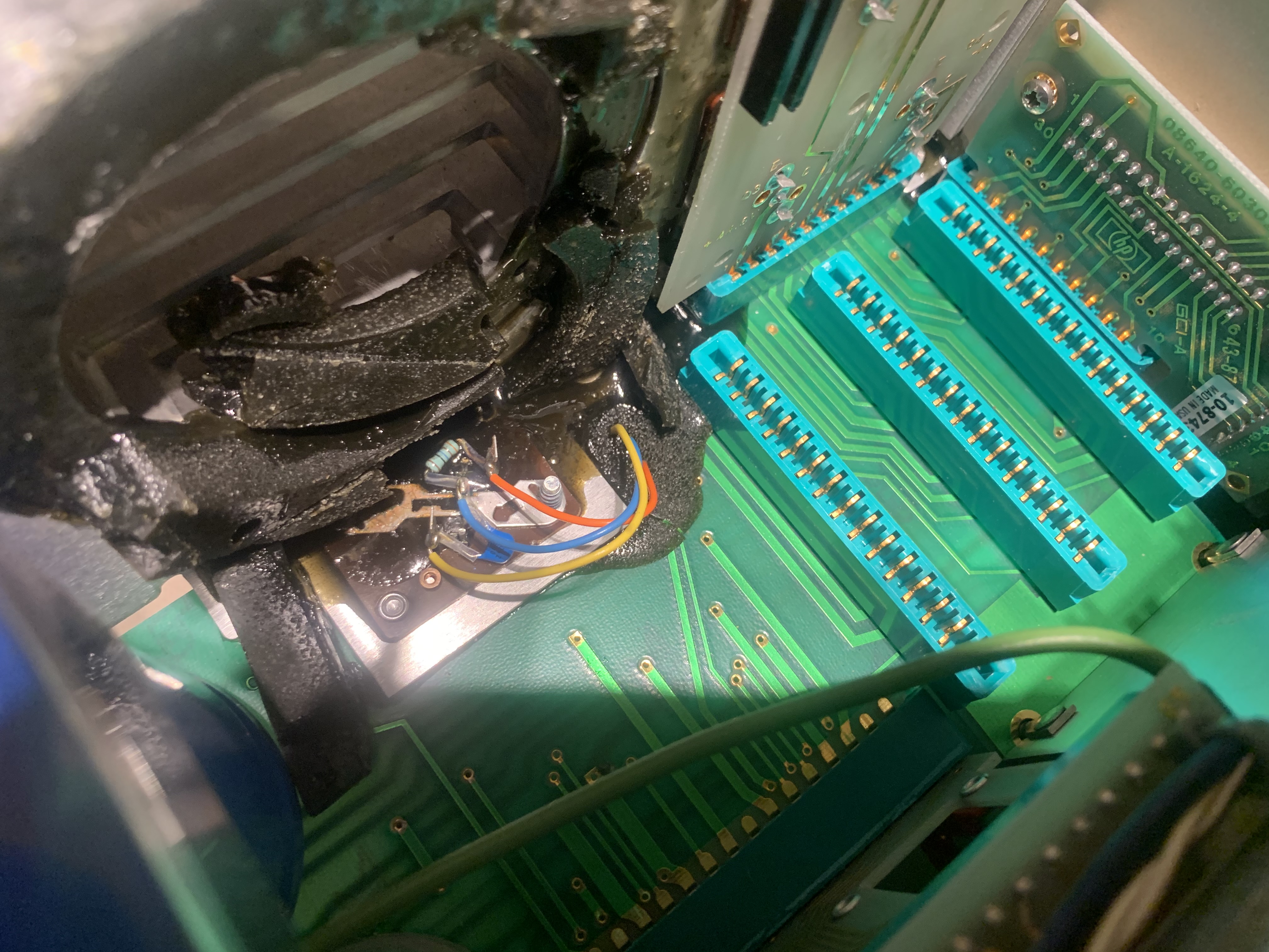
Wow. It almost looks like the foam rubber deteriorated from chemical attack and/or very high temperatures. Note the TO-3 socket covered in goo, that’s the same TO-3 package shown earlier in the board cutout of the power motherboard. Beyond the goo, the tin plated connector strap to the TO-3 case is oxidized and discolored. The goo appears identical to uncured epoxy, but I don’t know. Just to be sure all I pulled all the electrolytics adjacent, thinking that surely that’s where its coming from.
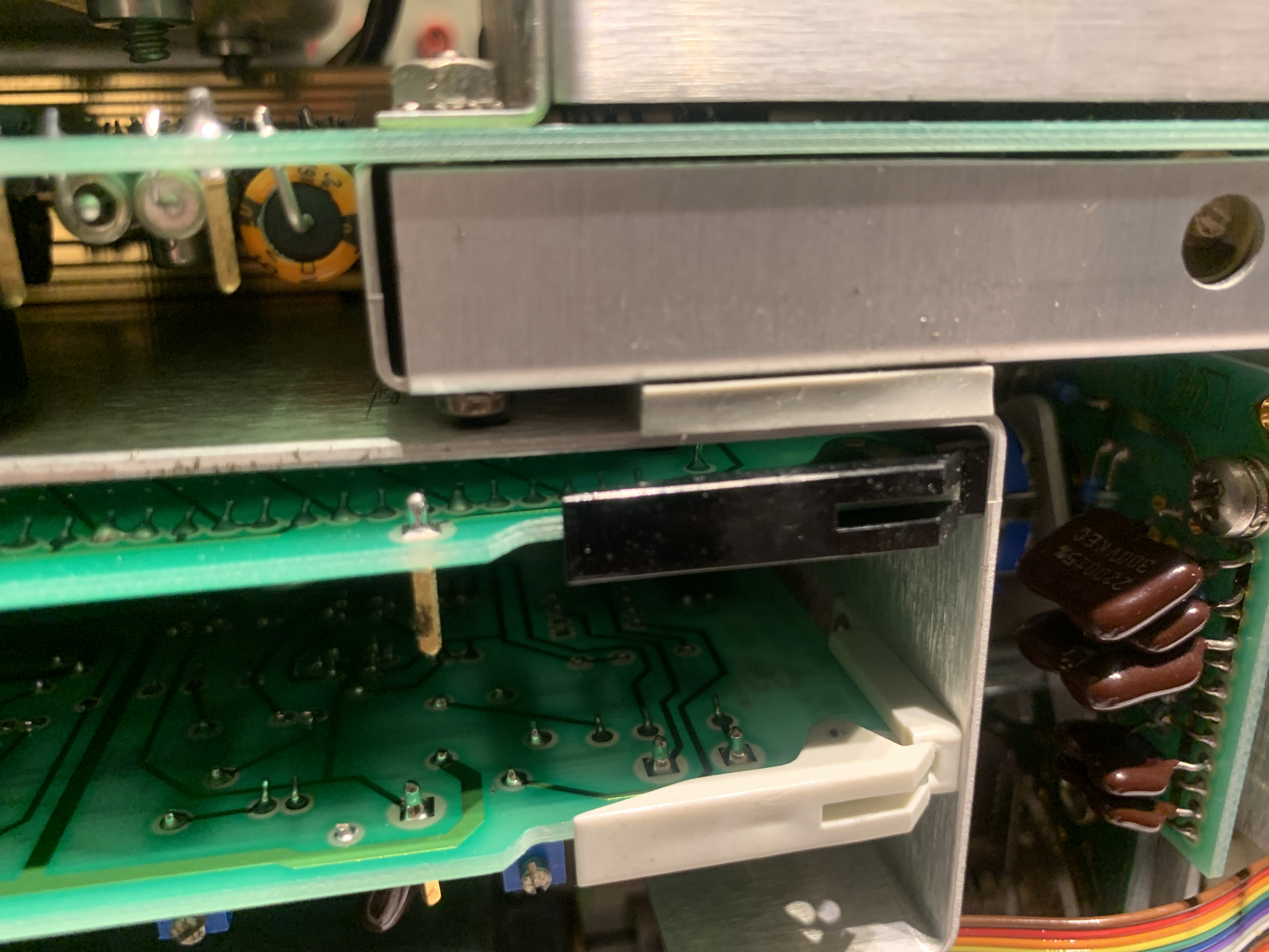
Nope, no leaks. I went ahead and checked the caps, all within tolerance. Then I notice the 4 slot external pass transistor mounting PWB mounted to the rear plate (See pic above top-middle, the card with the pwb guide rail that plugs into the power motherboard.). This is card 08640-60007 and has the quad TO-3 pass transistors. Lots of goo packed behind the PWB and the panel, covering the sockets and what-not. I decided to remove all the external pass transistors from the rear sink and pull the pass transistor PWB.
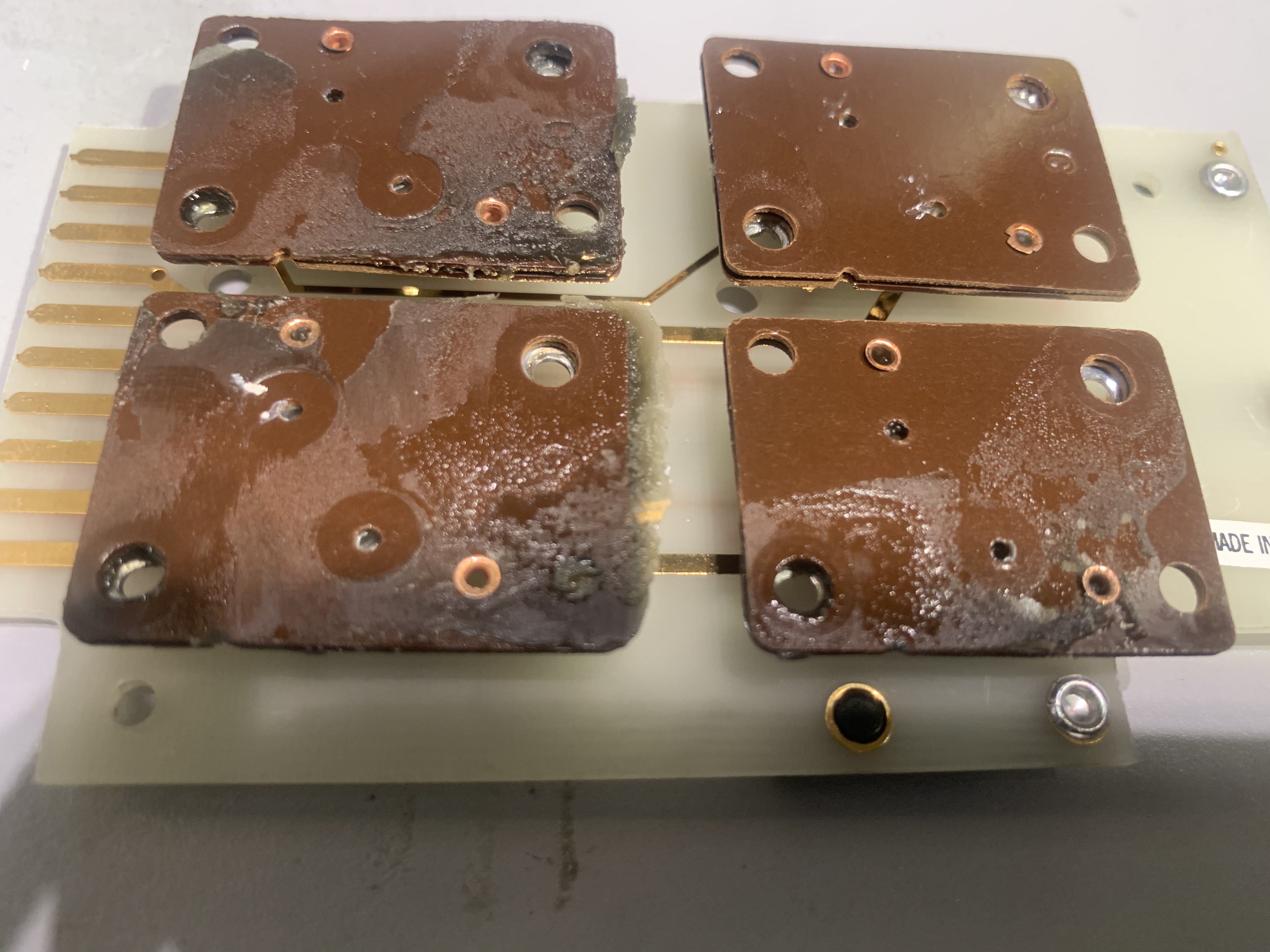
Yuck ! I tried cleaning this up, and it looked a lot better. BUT..do I really want to rely on goo immersed connectors ? Nope….Looks like standard Keystone stuff, none on hand so ordered them. It looks like the same socket used on the single TO-3 also damaged, so ordered enough for everything.
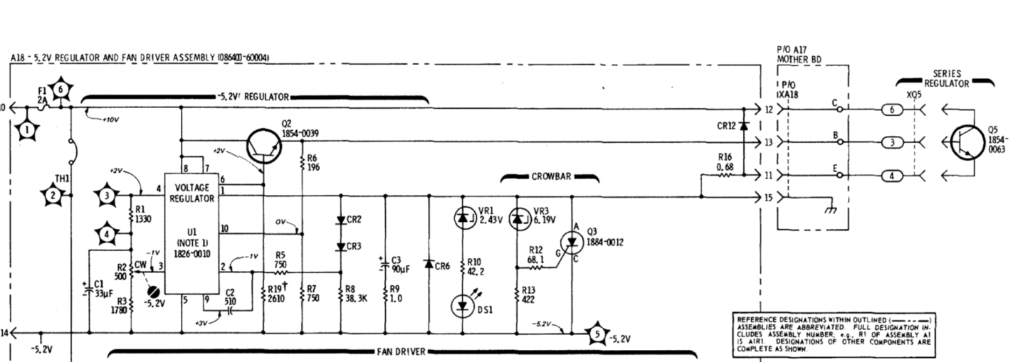
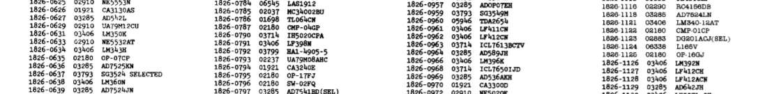
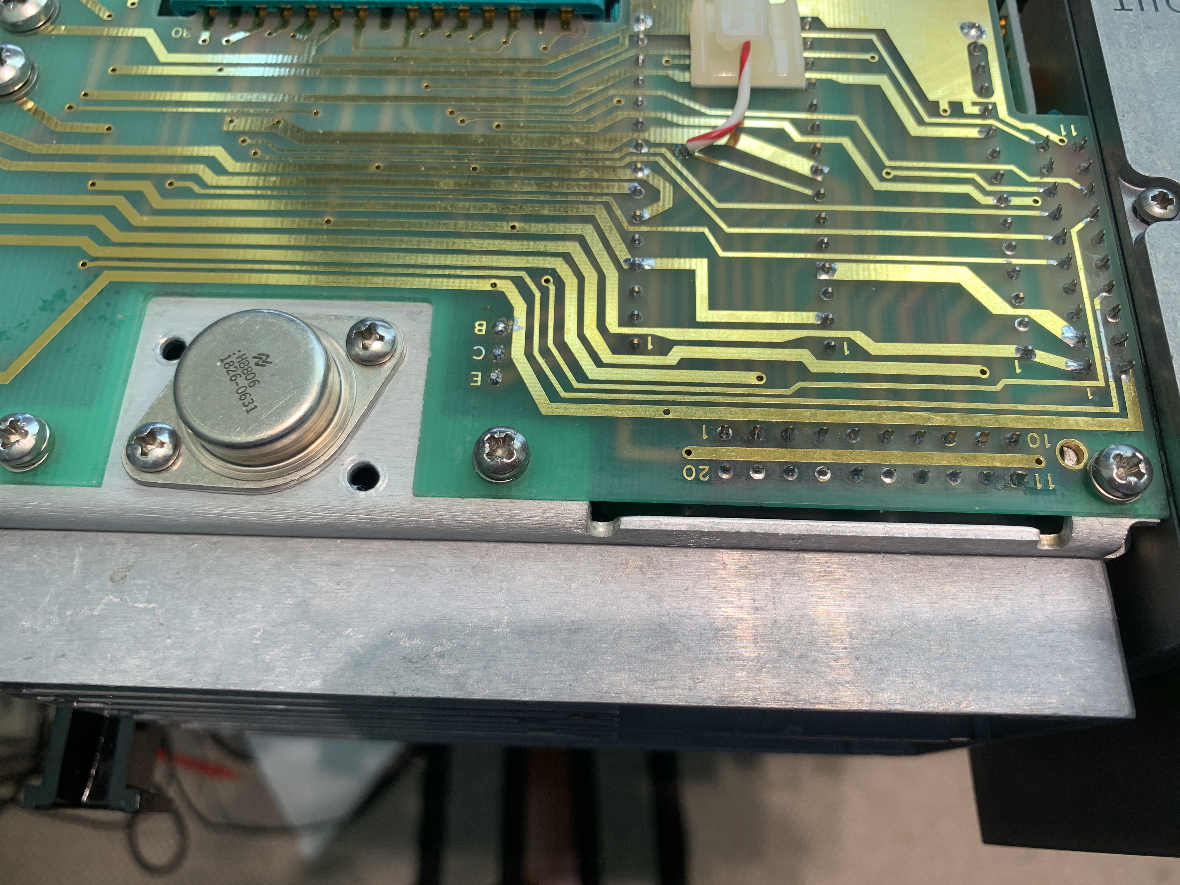
Time to move on and clean up this mess so I can repair. Luckily, the goo seems to remove fairly easy with elbow grease and alcohol. I ended up filling an entire wastebasket with goo infused Kim wipes, but could have been a lot worse. Before going any further, I checked all the external pass transistors. All the 4 pass transistors on the rear heat sink checked fine. Unfortunately, the -5.2v pass transistor Q5 p/n 1854-0063 shown in the following diagram is bad. Even more unfortunate is the part number, obviously a special. We need to find a suitable replacement. I have two numbers I’m trying to work with…the part # in schematic, and part # on the transistor. Transistor p/n is 1826-0631, the schematic shows 1854-0063. Probably due to the age of the manual I have. Looking at my handy cross-ref to jedec list, the 1854-0063 schematic # crosses o a 2N3055…no problem there. The physical part marked 1826-0631 doesn’t appear in any cross-ref guides I can find. The normal searches didn’t turn anything up, but I did manage to find the 1826-0631 via Quest Components. It’s shown as a National Semi part, which matches the national symbol on the physical part. Pricey, but in for a penny, in for a pound.
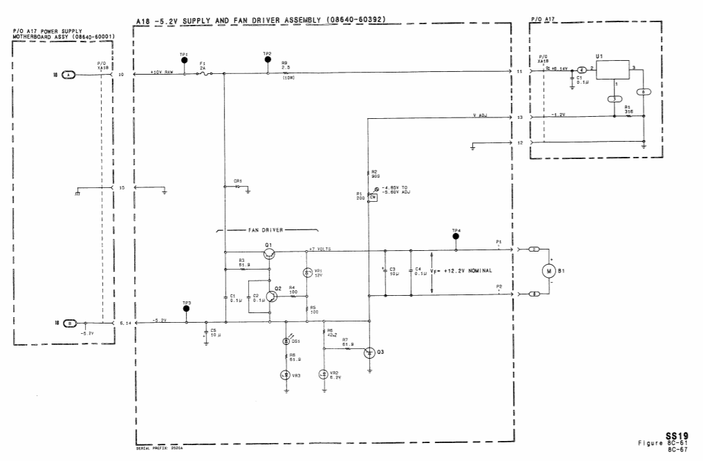
While looking at that, I figured I better walk my way back through the power system. The fan control board and -5.1v regulator is significantly different from the board shown in the schematic. I need to try and find a schematic for that part, but it’s not terribly complicated to trace through. Gone are the 723 regulator based parts on the board, it looks like a pretty simple circuit with a couple transistors and passives. There is a fuse labeled F1 which is currently blown. This is a BUSS GMW type 2A 125v, none on hand ordered stock from Mouser.
During the overall inspection, it was noted that the modulation frequency knob had a lot of lateral play. This needs to be investigated, as the play is approaching .250″. From the internal side, the entire modulation board is free to shift laterally.
Managed to find a more recent manual from ’91 on the Keysight website. This shows the most current pwb’s that are installed in this unit.
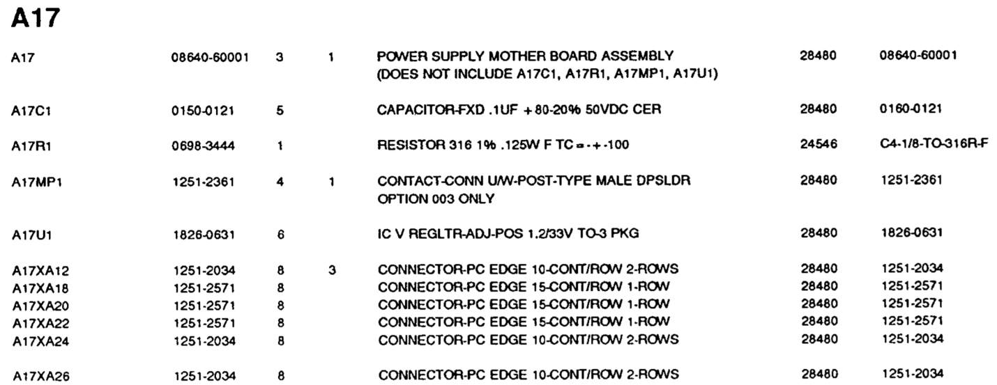
Here’s the parts list for the A17 board:
And the A18 board:
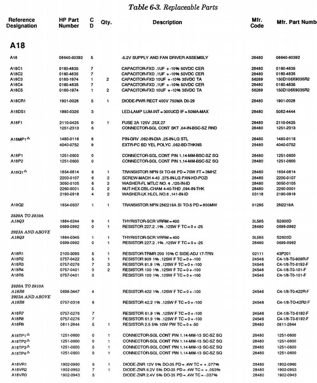
So ok, quite a few changes from the original fan control/-5.2v regulator. First off, There is no external pass transistor here, it’s a 3-terminal negative regulator. This looks like an LM337 but has the HP number 1826-0631. On the A17 board, there is a resistor & capacitor which is physically mounted to the TO-3 socket. The schematic shows 316 ohms and .1 mfd for these. I measured the damaged socket with the resistor mounted and it reads 314 ohms, so everything matches. Need to order replacements rather than reuse the damaged components.
So, I have a game plan now to repair the goo damage…
- Replace 4 Keystone sockets on the power pwb & reassemble rear heat sink w/ transistors
- Replace single TO-3 Keystone socket on rear panel (this is currently riveted, will need to be drilled out & remounted.
- Mount new 316 ohms & .1 mfd 50v to new keystone socket
- Replace F1 on the fan control 5.1 Reg Board.
- Remount Electrolytics & polycarbonate protection cover.
- Figure out how to mount the fan correctly
- Reassemble the unit
- Investigate the loose modulation board
- Replace missing escutcheon nuts for top/bottom case lids.
- Final inspection & unpowered test
The good news is, this is all really simple stuff so far. It looks like the goo took out U1 which likely caused -Vout to go more negative, which crowbared the supply via Q3, which opened F1. I managed to find all the components, but it will probably take a week or so to get all the parts here. I actually found the HP replacement for U1, so that was really the only item in question.
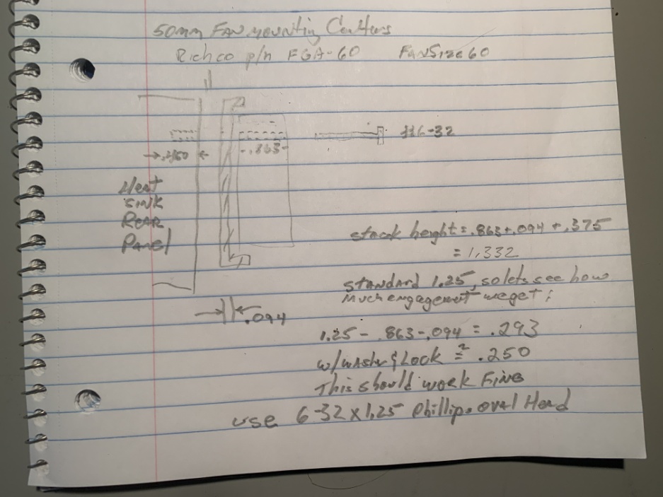
Now on to the fan mounting problem. When I disassembled the unit for the first time, the rubber gasket had failed as previously noted. After looking at the fan fit the gasket height will affect how all this goes together. Let’s review the mechanical assembly for the rear fan using the latest manual.
Unfortunately the updated manual I have has poor scanning and the mechanical bits are undecipherable. We can back engineer this easy enough. The fan is a standard size 60 that is normally mounted to the rear panel via a vibration isolator (now disintegrated). Looking at the internal real estate, a really simple solution is to add a standard size 60 fan gasket to the rear panel side of the fan, and shorten the 4 fan attachment bolts to accommodate the shorter standoff from the rear panel. I verified the rear plate clearances, and this should work well. I really want to keep the original fan, so I tested it for bad phases,etc. and all is fine. All I need is a fan gasket that will fit the original. It’s a standard size 60 so I did a quick Google to Richco part # FGA-60. This is available at Digikey P/N RPC1515-ND.
https://www.digikey.com/product-detail/en/FGA-60/RPC1515-ND/3811940
The 4 bolts will need modified heights (see next figure), which gives us a new bolt spec of 6-32 x1.25 oval head Phillips 304ss.
OK, looks like we have a pretty good plan in place for the fan gasket replacement. I pondered for awhile as to why the original gasket was so far extended. From an airflow perspective, there is no perceptible shift in the airflow patterns as the fan offset from the rear panel increases. The only thing that comes to mind is with a thicker gasket of appropriate durometer much better vibration performance is possible. I honestly don’t think a bit of fan vibration is going to affect the instrument, based on a quick vibration check of the existing fan.
And I’m still struggling with why the damn gasket deteriorated like that.
Repair Sequence
I had some spare time, and not all of the components are received yet, so I decided to get a started on fan repair. I modified the design slightly in order to give the fan mount a bit more compliance to reduce vibration & noise I added a simple 2-006 o-ring beneath the fan mount bolt heads. I opted for an oval-head to keep everything self-centered. Installed body gasket, & loctite 242. Torque to 3-4 in-lbs.
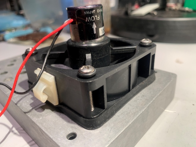
Final assembly with compliance gasket & o-ring floats
5.1v Regulator Repair
I ordered two different style sockets for this, the stock replacement from Keystone #4606 & and a oval profile plastic insulated one Keystone #4732. It looks like I can use the #4732 from dimensions & clearances, so I’m going with that (I like the fact that the plastic is there with a phenolic base, a bit more rugged than the original). Same shitty TO-3 mounts, but a #6-32 works good here (throw away the self-tapping screws).
I drilled out the existing rivets, removed the original goo soaked socket and cleaned everything well. Now I just got a call from my supplier and the oem TO-3 regulator is not available. All things considered, I’m going to look at the National part again.
I pulled up a different cross-ref and found the HP1826-0631 crosses to a LM350K.
https://doc.xdevs.com/doc/HP_Agilent_Keysight/HP Master Xref.pdf
I’m going to assume we’re good with the ratings, the LM350K is rated for 33v, 3A. I triple checked to make sure the LM350K standard pinout matches the oem regulator pinout. I found one in my NOS stock, so there’s an option.
I forgot to note that the regulator is a positive adjustable, not a negative regulator. In the meantime lets test the regulator for fun…
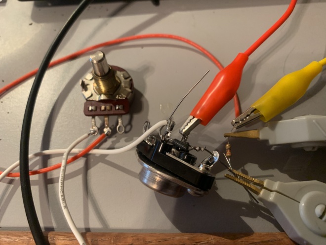
Did a quick setup for 5.2v output, vin=20v
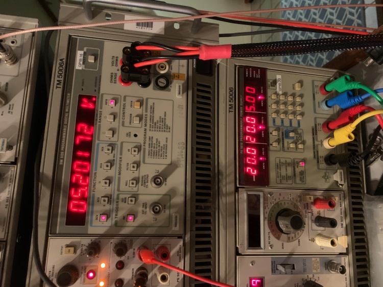
The output tracks properly, Vref is accurate. Since this seems to be working fine, I’m going to replace it in the unit.
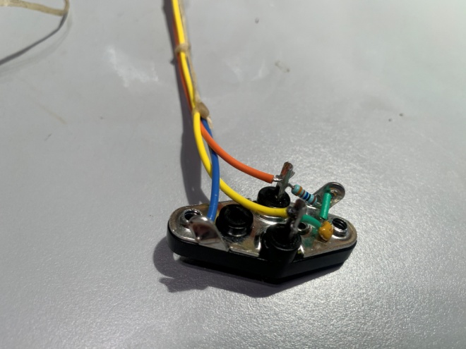
edit- Those Keystone sockets suck. I changed to a proper TO-3 socket here, TE# 8080-1G1. Much better, here is the prepped socket with components & lead wires for attaching to the power motherboard.
Ok, time to reassemble the -5.1v regulator onto the rear panel
The case of the regulator is at ground potential (grounded output), so no TO-3 insulators are required. I used a high conductivity (heat!) thermal compound chip-kwik TC2-10G to coat the rear face of the TO-3 and reassemble. Note that all four rear panel TO-3 pass transistors were mounted via anodized aluminum heat wafers. These act as insulators as long as the surface finish isn’t scratched. In my case they all looked great, so simply mounted the transistors using the thermal paste on either side of the aluminum wafer. The alignment of the transistor board looked really iffy to me. The original was warped and was likely due to having the socket heights wrong on the board. To solve that, I assembled everything dry, and once everything was aligned properly, only then did I solder the sockets to the transistor board. Now that the alignment is correct, the transistors, etc. can be replaced/serviced normally.
Ok, we’re pretty much done here for a systems check. Let’s have a look at the results:
This the bottom side showing the replaced -5.1 regulator (note the drilled out rivets, holes no longer needed).
Reinstalled original HP regulator. Note the ECB notations on the power motherboard, This is an artifact of earlier gen using an external pass transistor instead of a regulator.
Top view- Modifications and repairs to power supply section complete.
Wet-Test
Not much opportunity to do power isolation checks, as there is not really a good way to fire up the supplies independent of the instrument. Hopefully, the crowbar circuits and fuses will protect from any issues…..
OK…awesome !…I applied power for a few seconds, all the supply indicators look right, and the fan is running. Checked the supplies, everything is within tolerance. Let’s see if our repairs solved anything.
Powered the unit back up facing the front panel. Awesome, we have a frequency counter showing internal frequency. Ran the output to a scope and yup, there be RF 🙂 Let’s see what works and what doesn’t:
1. RF output is functional, attenuator seems to work smoothly no issues.
2. Checked AM & FM modulation, everything works there.
3. Level position switch on the meter panel does not function properly. Level switch will not fully depress. A little silicone lubricant on the switch assemblies took care of that.
4. Range switch may have some issues. When switching bands, the output is distorted for 1-2 seconds before stabilizing, particularly on the HF end.
5. Main tuning knob functions ok. A slight drag as it approaches the LF end. I removed the setscrews from the tuning knob, removed & cleaned. Reinstalled tuning out any eccentric movement during rotation. Works fine now.
6. Counter phase lock function works as intended.
7. Frequency accuracy seems to be good, ran to a counter and they agree within 100 hz or so @500 Mhz using a calibrated counter.
At this point, we have a functioning generator but we need to look at the range switch (yikes) . The range switch assembly has two circular sliprings comprised of conductive fingers and concentric gold plated rings. Nothing obvious, so I just added a touch of silicone lubricant and cycled the range switch a dozen times. Voila ! problem solved. No more distortion or hesitant behavior. I’m going to call this one done unless it reappears. It’s not a daunting task, just tedious to jack with the range switch. I’ll do a more thorough job if (when?) I have to replace the plastic gears.
Next I looked at the wobbly modulation board. I discovered a broken plastic support post that secures the modulation assembly to the front panel.
Looking at this, I really don’t think I can repair the existing post. I might be tempted to cyano-glue the thing, but it would be temporary at best. Rather than do that, I discovered that if I add a rubber pad back at the modulation board stack, the majority of the motion disappears. I’ll make a mental note to do something more original if I ever have to pull the front panel.
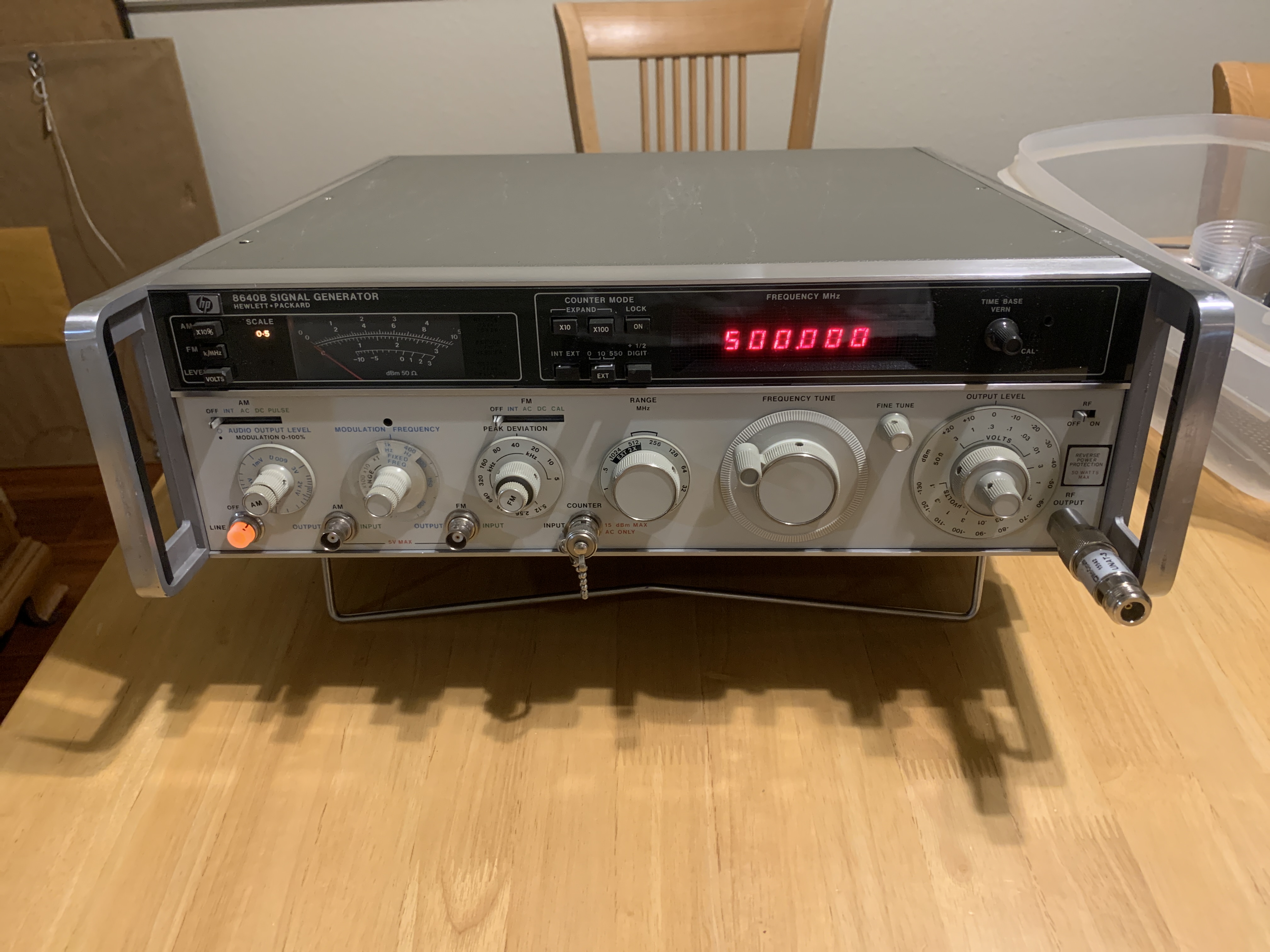
And here she is all put back together, phase locked at 500Mhz 🙂
Thats all for now !! The next post we’ll run it through its paces and see how good it is in reality. I’m really happy with this unit. Dirt cheap, simple repair, cosmetics are great. Someone took care of this unit, always a surprise but welcomed. The only thing that would have been better would be the internal doubler, but I have an HP external doubler I can use to make it think it has one.